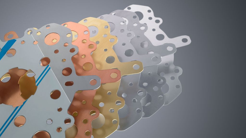
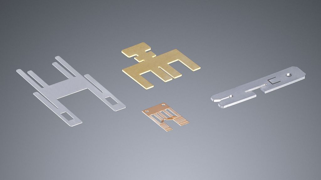
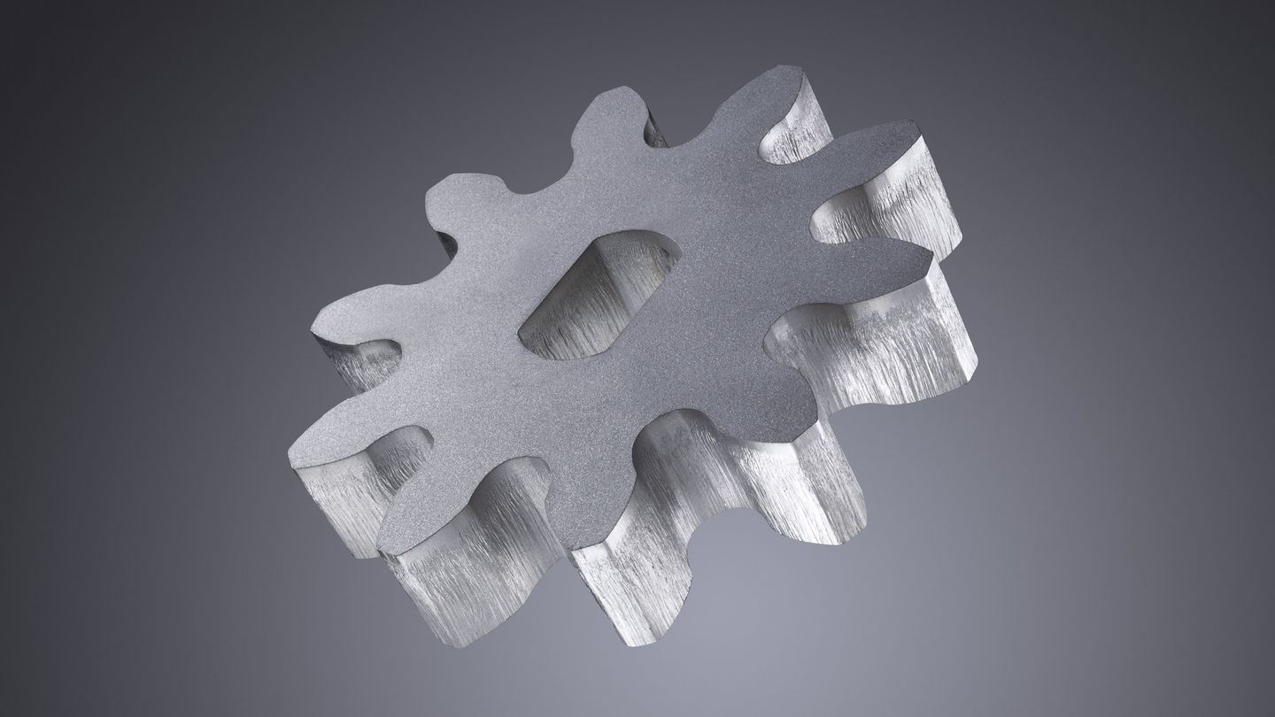
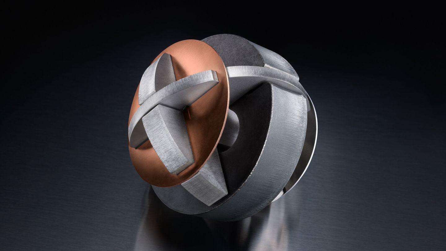
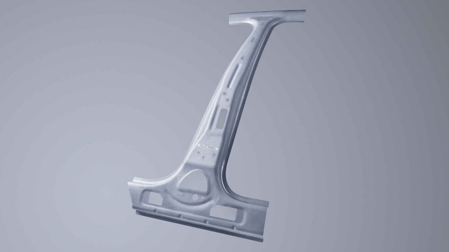
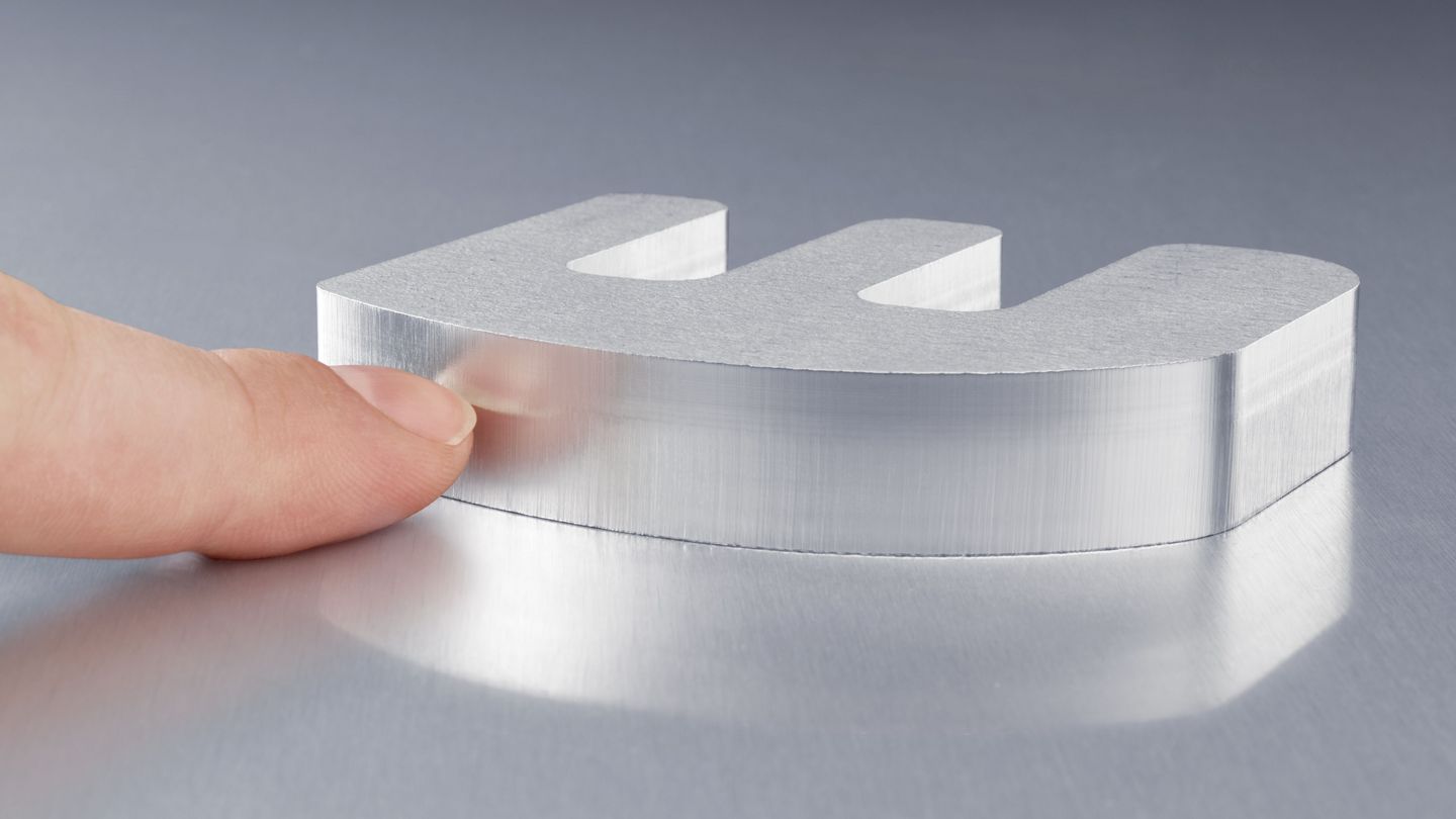
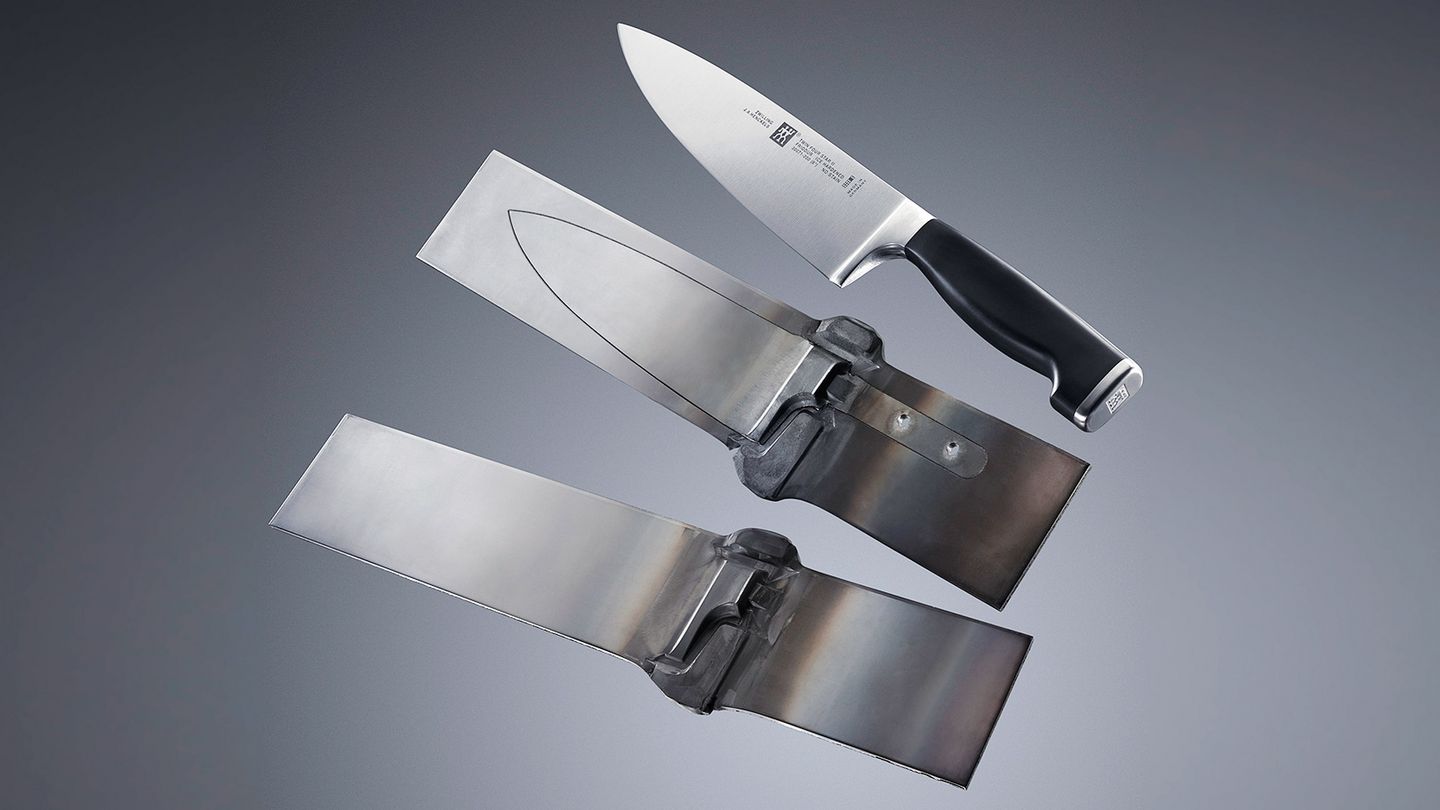
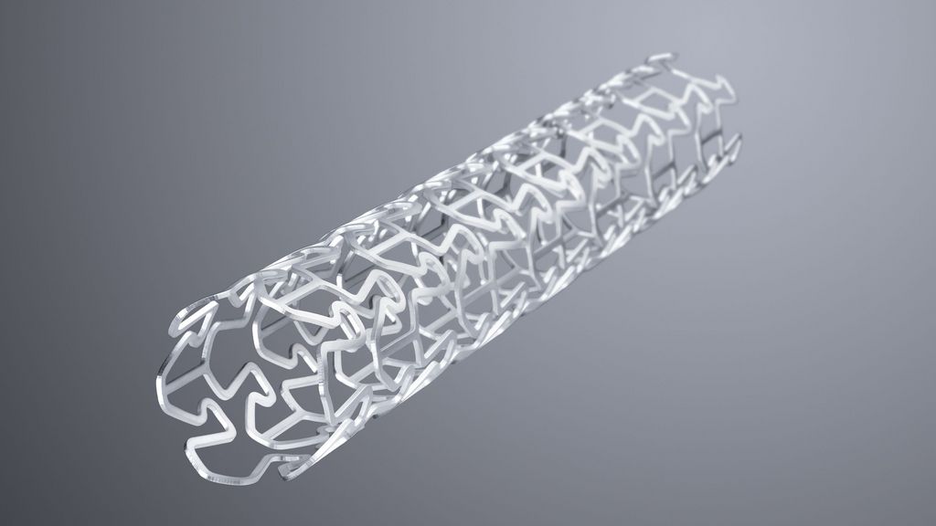
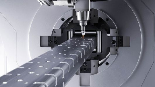
All materials common in industrial processing – from steel to aluminium, stainless steel and non-ferrous metal sheets, all the way to non-metal materials such as plastics, glass, wood or ceramics – can be cut safely and in high quality with the laser. Very different sheet thicknesses of 0.5 to over 30 millimetres can be cut using the tool. This extremely wide material range makes the laser the top cutting tool for many applications in the area of metals and non-metals.
Laser cutting as a contact-free slitting process
Laser cutting is a slitting process with which it is possible to cut metallic and non-metallic raw materials of different material thicknesses. This is based around a laser beam which is guided, formed, and bundled. When it hits the workpiece, the material heats up to the extent that it melts or vaporises. In this process, the whole laser power is concentrated on one point, with a diameter that is often less than half a millimetre. If more heat is introduced into this area than can dissipate through heat conduction, the laser beam will penetrate the material entirely – the cutting process has begun. While other processes involve applying large-scale tools with enormous power to the sheet metal, the laser beam completes its task without any contact. In this way, the tool does not incur wear, and no deformities or damage to the workpiece occur.
Advantages of laser cutting
Discover our products for laser cutting
Whether 2D or 3D laser processing – TRUMPF offers machines and systems for extremely various applications for you.
Laser cutting processes compared
In our technology comparison, you can see the advantages and disadvantages of laser cutting compared to the conventional slitting processes of flame cutting and plasma cutting.
The laser cutting process
The interaction between a focussed laser beam and workpiece forms the basis of laser cutting. In order for this process to be carried out reliably and precisely, numerous components and additional equipment are used on and around the laser beam, which will be illustrated in the following graphic.
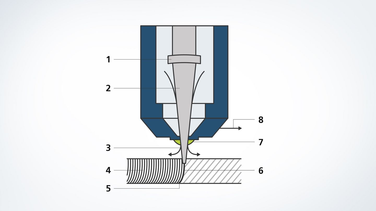
- Focussing optics: lens and mirror optics focus the laser beam on the processing point
- Laser beam: the laser beam hits the workpiece and heats it up until it melts or vaporises.
- Cutting gas: the resulting melt is blown out of the kerf using cutting gas. The gas is emitted coaxially with the laser beam from the nozzle.
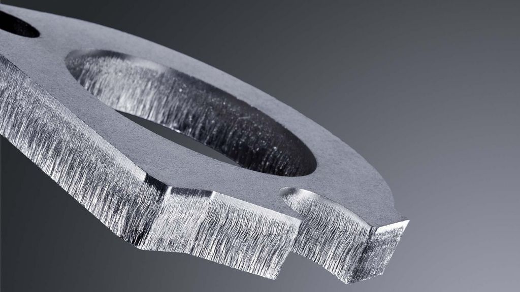
- Drag lines: during laser cutting, the cutting edge is given a typical drag line pattern. At a lower cutting speed, these drag lines are virtually parallel to the laser beam.
- Melt: the laser beam – bundled laser light – is guided along the contour and melts the material locally.
- Cutting point: on the workpiece, the kerf is barely wider than the focussed laser beam.
- Nozzle: laser beam and cutting gas meet the workpiece through the cutting nozzle.
- Cutting direction: the kerf is created by moving the cutting head or the workpiece in a specific direction.
Various applications in the area of laser cutting
All laser cutting procedures at a glance
When it comes to cutting metal and non-metal raw materials, the laser is in many cases the first choice as a universal tool. The laser beam cuts nearly any contour quickly and with flexibility – regardless of how intricate and complex the shape is, or how thin the material. In the process, various cutting gases and pressures influence the machining process and the result.
For flame cutting, oxygen is used as the cutting gas; this is blown into the kerf with a pressure of up to 6 bar. There, it burns and oxidises the metal melt. The energy generated by this chemical reaction supports the laser beam. Flame cutting allows for very high cutting speeds and the processing of thick sheet metals and mild steels.
During fusion cutting, nitrogen or argon are used as a cutting gas. This is driven through the kerf with a pressure between 2 and 20 bar, and unlike flame cutting, does not react with the metal surface in the kerf. This cutting procedure has the advantage that the cutting edges remain free of burrs or oxides, and reworking is barely required.
Sublimation cutting is primarily used for precision cutting tasks which require very high-quality cutting edges. In this process, the laser vaporises the material with as little melting as possible. The material vapour creates a high amount of pressure in the kerf, which forces the melt out in an upwards and downwards direction. The assist gas – nitrogen, argon or helium – shields the cutting areas from the environment and ensures that the cutting edges remain free of oxides.
For laser beam precision cutting, individuals bores are joined together with pulsed laser energy; these overlap by 50 to 90% and form a kerf. The short pulses create very high levels of peak pulse powers and extreme irradiances on the workpiece surface. The advantage: heating up of the component is very minimal, which allows for the cutting of even the most intricate parts without heat distortion.
Parameters which influence the laser cutting process
The focus position influences the irradiance and form of the kerf on the workpiece. The focal diameter determines the gap width as well as the form of the kerf.
So that the processing threshold – the point at which the material begins to melt – is exceeded, a specific amount of energy per surface area unit is required. This is defined as: energy per surface area unit = irradiance x exposure time on the workpiece.
Choosing the right nozzle is crucial for part quality. The form of the gas beam as well a the gas quantity are determined by the diameter of the nozzle.
Continuous wave operation or pulsing – the operating mode allows you to control whether the laser energy is to hit the workpiece continuously or with interruptions.
The respective cutting task and the material to be processed determine the cutting speed. As a basic rule: the more laser power that is provided, the faster the cutting can be carried out. Additionally, the cutting speed is reduced with increasing material thickness. If the speed for the respective material has been set too high or too low, increased surface roughness and burr formation can occur as a result.
Nearly all CO2 lasers deliver linear polarised laser light. If contours are cut, the cutting result changes with the cutting direction: if the light oscillates parallel to the cutting direction, the edge will be smooth. If the light oscillates perpendicular to the cutting direction, this creates a burr. This is why linear polarised laser light is often switched over to circular polarised. The degree of polarisation determines how well the target circular polarisation was reached, and is decisive for cutting quality. Polarisation must not be changed for solid-state lasers; it delivers direction-independent cutting results.
Different process gases are used depending on the cutting procedure; they are driven through the kerf at varying pressures. Argon and nitrogen as cutting gas, for example, have the advantage that they do not react to the melted metal in the kerf, while at the same time shielding the cutting area from the environment.
Burrs in mild steel and aluminium can be reduced when combining high laser power with the application of a gas mixture of nitrogen and oxygen. The improvement in part quality depends on the material type, material alloy and material quality in thick sheet ranges between six to twelve millimetres.

